Choosing a Pin Header Connector in 2026 is not just a matter of matching pin count. The right choice depends on electrical demands, board layout, assembly method, and the conditions the finished product will face. A connector that works well on a quiet sensor board may be unsuitable for a vibrating industrial controller. Small details matter.
This guide explains how to compare pitch, pin arrangement, current rating, plating, mounting style, and mating compatibility. For example, a 2.54 mm pitch header is common and easy to prototype with, while tighter pitches can save board space but demand more precise assembly. Straight and right-angle headers also change cable routing and access. Check the datasheet, not just the product photo. Ratings can vary between similar-looking parts, and current limits may depend on temperature rise and the number of energized pins.
The goal is to help engineers, buyers, and makers narrow choices with evidence rather than guesswork. We will consider standard options, specialized applications, and practical checks before ordering samples or approving production. A perfect connector does not exist. Trade-offs remain, especially between size, durability, cost, and ease of replacement. Some recommendations may also need revision when a design’s environment or manufacturing process changes. Use the criteria here as a starting point, then verify them against the actual board, mating component, and operating conditions.
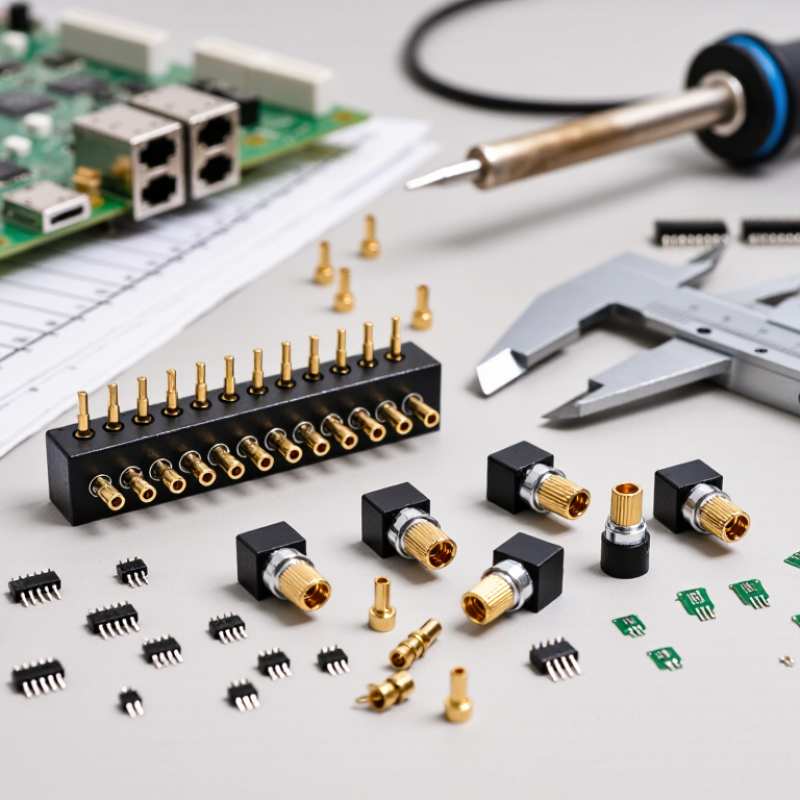
What Is a Pin Header Connector and Where Is It Used?
A pin header connector is a simple electrical interface with parallel metal pins inside an insulating housing. It joins circuit boards, wires, sensors, and control modules through matching sockets or cables. The pins usually use a regular spacing, such as 2.54 mm, although compact equipment may require smaller pitches.
You can find pin headers in development boards, industrial controllers, test equipment, and consumer electronics. They support power, signal, and programming connections. In real projects, I have seen a small pitch create difficult inspection and repair work. A larger pitch may be easier to handle, but it can consume valuable board space. The right choice depends on current, voltage, pin count, contact direction, and installation conditions. Vibration also matters. A loose connection can cause intermittent faults that are hard to reproduce.
Tips: Check the mating connector before ordering. Confirm pitch, pin length, row count, and mounting direction. Choose gold-plated contacts for frequent connection cycles, when justified. For dusty or vibrating environments, consider a shrouded design or a locking feature. Do not select by appearance alone. Testing a sample under real temperature and movement conditions is safer. Even careful engineers sometimes overlook cable clearance. That detail deserves another check.
Which Electrical and Mechanical Requirements Must It Meet?
Choosing a pin header connector in 2026 requires more than matching pin count and pitch. The electrical specification must fit the circuit’s real operating conditions. Check rated voltage, continuous current, contact resistance, insulation resistance, and dielectric withstand voltage. High-speed signals may also require controlled impedance and reduced crosstalk. Do not trust a general-purpose part without reviewing test data.
Mechanical requirements deserve equal attention.
Confirm the pin pitch, row arrangement, mating height, PCB thickness, and mounting method. Through-hole pins usually resist vibration well, while surface-mount versions can save board space. Verify the connector’s retention force and rated mating cycles. A loose connection can appear acceptable during assembly, then fail after repeated service.
Temperature matters.
So does vibration.
In practical evaluations, I inspect samples with the intended cable, housing, and PCB, not alone. I measure insertion force and contact resistance before and after cycling. I also check pin coplanarity under magnification. Small alignment errors can create uneven solder joints. The tempting shortcut is choosing the cheapest compatible header. I have found that this often ignores plating thickness, tolerance control, or heat exposure during assembly. Still, no checklist is perfect. Actual equipment may reveal stress that laboratory tests miss. Leave space for inspection, repair, and future revision.
How Do Pin Count, Pitch, Orientation, and Mounting Style Affect Selection?
How to Choose a Pin Header Connector in 2026?
Choosing a pin header begins with the circuit, not appearance. Pin count must match every signal, power line, and reserved position. Leave space for future changes when the board allows it. A connector with too few pins creates awkward jumpers. One with too many may waste board area and increase cost. Pitch also matters. Fine pitch saves space, but it demands accurate PCB fabrication and careful inspection. Wider pitch usually offers easier assembly and stronger mechanical tolerance.
Orientation affects cable routing and enclosure clearance. Vertical headers suit direct board-to-board connections. Right-angle headers guide cables along the board edge. Check the mating direction inside the finished enclosure, not only in a computer model. Mounting style is equally important. Through-hole parts often resist repeated insertion forces. Surface-mount versions support compact layouts and automated assembly, but their solder joints may need extra mechanical support. I have seen suitable connectors fail because mounting loads were ignored.
Tips: Print the connector outline at full scale. Place it on the real enclosure. Check pin numbering, keying, solder temperature limits, and mating clearance from the datasheet. Test a sample assembly before production. Small mistakes become expensive quickly. Also, review the design after vibration, cable bending, and repeated connection tests. No selection is perfect. A slightly larger pitch may be wiser than a fragile, space-saving choice.
How to Choose a Pin Header Connector in 2026?
How do pin count, pitch, orientation, and mounting style affect selection?
This chart compares the theoretical number of contact positions that can fit in a 100 mm row at common pin-header pitches. Values are calculated as 100 ÷ pitch and represent geometric spacing, not a specific product rating. Choose pin count according to the required circuits, use a smaller pitch when board space is limited, and confirm that the selected vertical or right-angle orientation and through-hole or surface-mount style match the PCB layout and assembly process.
Which Materials, Plating, and Manufacturing Features Matter in 2026?
How to Choose a Pin Header Connector in 2026?
Material selection affects strength, conductivity, and long-term stability. Copper alloy contacts provide reliable current flow and resist repeated bending. Phosphor bronze offers better spring recovery for connectors exposed to frequent mating cycles. For the insulator, nylon suits general equipment, while high-temperature plastics perform better near motors, power supplies, or reflow processes. Check the actual operating temperature, not only the catalog rating. Heat changes everything.
Plating deserves careful attention. Tin plating is economical and works well in many low-cost, protected environments. Gold plating supports cleaner contact performance, especially with low signals or repeated mating. A nickel barrier can reduce diffusion and improve surface durability. However, thicker plating is not automatically better. The wrong finish may increase cost without solving oxidation, vibration, or humidity problems. In my experience, testing the connector after temperature cycling reveals weaknesses that a visual inspection misses. Small details matter.
Tips: Match contact plating with current, signal level, mating frequency, and environment. Review terminal retention, pin alignment, coplanarity, and solderability. Ask for material certificates and test data, then inspect samples under magnification. Manufacturing consistency often matters more than impressive specifications. Leave tolerance for assembly variation. Perfect drawings can still meet imperfect production.
How Can You Test Compatibility and Evaluate Suppliers?
How to Choose a Pin Header Connector in 2026?
Compatibility testing should begin with the mating parts, not the catalog page. Measure pitch, pin count, row spacing, and body height with a caliper. Check the contact direction and keying features. A connector may look identical but fail after a small offset. Test the required current and voltage under real temperature conditions. Inspect solder joints under magnification. Then perform continuity and insulation-resistance checks.
Do not trust one sample. Use several connector pairs from different production lots. Cycle them repeatedly, especially if equipment will be serviced often. Watch for loose contacts, bent pins, housing cracks, and rising contact resistance. Thermal cycling can reveal problems that a clean bench test misses. Humidity exposure matters too. A spreadsheet can still lie. Record photos, test settings, failures, and operator names for traceability.
Supplier evaluation requires evidence beyond a low quotation. Ask for material specifications, plating thickness, tolerance data, and independent test reports. Review quality certificates, process controls, change-notification procedures, and lot traceability. Request samples made with the intended tooling. Production samples are more meaningful than polished prototypes. Visit the facility when volume or safety risk justifies it. Speak with the quality team, not only sales staff. I have seen promising parts fail because the mating force was never measured. That detail deserves attention.
FAQS
It is an electrical interface with parallel metal pins inside an insulating housing. It connects boards, wires, sensors, and control modules. Simple design.
They appear in development boards, industrial controllers, test equipment, and consumer electronics. They carry power, signals, or programming connections.
Pitch means the distance between neighboring pins. Fine pitch saves board space but demands accurate assembly and careful inspection. Wider pitch is easier to handle.
Count every signal, power line, and reserved position. Leave room for future changes when the board permits it. Too few pins create awkward jumpers.
Vertical headers support direct board connections. Right-angle headers guide cables along the board edge. Always check routing inside the finished enclosure.
Through-hole parts often resist repeated insertion forces. Surface-mount parts support compact layouts and automated assembly. Their solder joints may need extra mechanical support.
Measure pitch, pin count, row spacing, and body height with a caliper. Check keying, contact direction, and mating clearance. Test several connector pairs.
Perform continuity and insulation-resistance checks. Test current and voltage under real temperatures. Add repeated mating, vibration, thermal cycling, and humidity exposure.
Request material details, plating thickness, tolerance data, quality records, and lot traceability. Ask for samples from intended production tooling. Low price proves little.
Do not choose by appearance alone. Cable clearance, vibration, and mating force can be overlooked. I might still miss one during modeling, so test the real assembly.
Conclusion
Choosing the right Pin Header Connector in 2026 requires more than matching the number of pins. Start by identifying its application, such as board-to-board, wire-to-board, or connection to sensors and control modules. Evaluate electrical requirements including voltage, current, signal speed, insulation performance, and contact resistance. Mechanical factors are equally important: pin count, pitch, row arrangement, orientation, mounting method, available space, mating cycles, and resistance to vibration or temperature changes all influence long-term reliability.
Material and manufacturing quality should also be carefully reviewed. Contact metals, insulation materials, plating thickness, solderability, dimensional accuracy, and protective features can affect performance and service life. Before final selection, confirm compatibility through drawings, samples, mating tests, electrical continuity checks, and environmental testing. When comparing suppliers, consider production consistency, quality-control procedures, customization capability, technical support, traceability, delivery stability, and total cost rather than unit price alone. A well-matched connector should satisfy both current design needs and future maintenance or product expansion requirements.

 Dynalink Electronic