Global infrastructure is entering a demanding replacement cycle. The International Energy Agency’s Electricity Grids and Secure Energy Transitions report estimates that more than 80 million kilometres of grids must be added or refurbished by 2040. It also states that annual grid investment must rise above USD 600 billion by 2030. These figures explain why connection reliability matters beyond the equipment cabinet. A failed joint can delay commissioning, interrupt power, and create expensive site work.
Compression Connectors offer a practical response for many transmission, distribution, renewable-energy, and industrial projects. Installers use calibrated dies and specified crimping sequences to create a stable connection between conductors and terminals. The process is repeatable. It also reduces dependence on field welding, especially where access is limited or weather changes quickly. IEC 61238-1 provides testing principles for compression and mechanical connectors used with power cables. In North America, UL 486A-486B addresses wire connectors and solderless terminals. These standards support informed selection, but they do not replace correct installation.
That distinction matters. No connector is universally perfect. Conductor material, cable size, oxide layers, tooling condition, thermal cycling, and moisture exposure can change performance. Engineers should verify the manufacturer’s test data and project specifications before approval. Practical experience shows that a connector can look secure yet fail after repeated heating and cooling. Inspection is not optional. For global projects, Compression Connectors combine familiar installation methods with scalable quality control. Their value comes from disciplined engineering, not from the product name alone. IEA data supports the urgency, while field verification proves suitability.
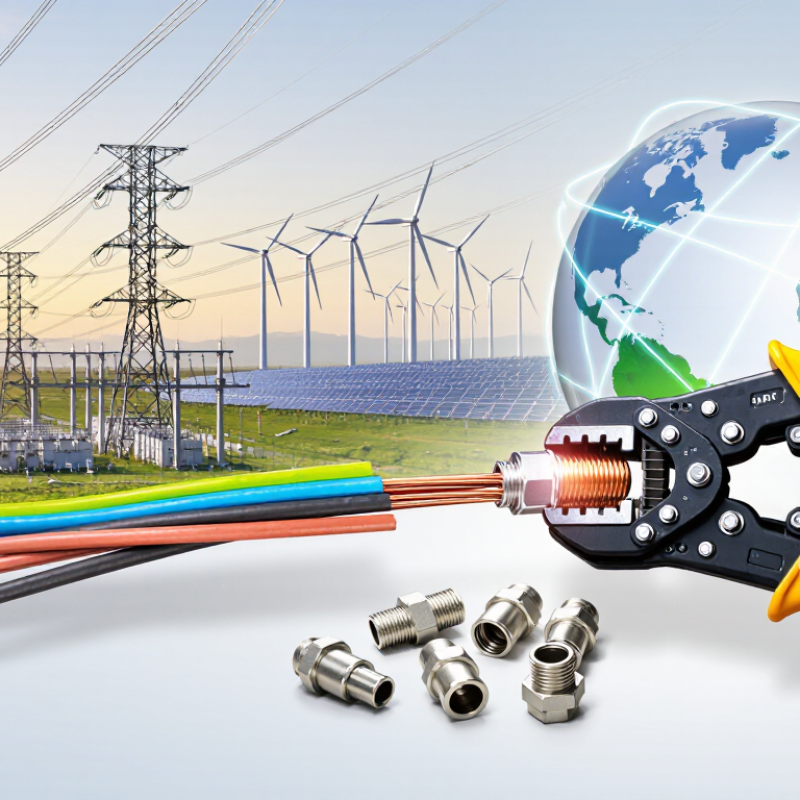
Compression connectors join electrical conductors through permanent mechanical pressure. They do not depend on threaded tightening or soldering. A correctly sized connector is crimped with a specified die, creating a stable electrical and mechanical connection. Picture a cable joint inside a hot substation cabinet: clean metal, controlled compression, and no loose fastener to retighten. IEC 61238-1 sets performance requirements for power-cable connectors. Its testing examines electrical resistance, temperature cycling, and short-circuit behavior. These criteria help international teams follow consistent practices instead of relying on local habits.
Global infrastructure is expanding quickly. The International Energy Agency’s Electricity Grids and Secure Energy Transitions report estimates that annual grid investment must exceed 600 billion dollars by 2030. That growth means more joints exposed to rain, vibration, heat, and rushed schedules. Compression connectors can simplify installation when conductor material, size, die geometry, and tooling match precisely. They also reduce the need for field heating equipment. Small detail. Still, they are not foolproof. Poor stripping can damage strands, while incorrect dies can leave hidden voids. Engineers should record tool calibration, compression marks, connector traceability, and installation conditions. Specifications should address aluminum conductors, corrosion control, and regional testing requirements. A connector is only as reliable as the process behind it.
Compression connectors join conductors through controlled mechanical pressure. A prepared cable enters a metal barrel or ferrule. The installer then tightens a nut or uses a compression tool. The connector deforms around the conductor strands. This creates a stable electrical path and resists loosening from vibration. Contact pressure also helps reduce air gaps, moisture entry, and oxidation. However, performance depends heavily on conductor preparation, correct sizing, and calibrated tooling.
The IEC 61238-1-1 standard evaluates electrical and mechanical performance through tests such as temperature cycling and short-circuit resistance. That matters as electricity demand expands. The International Energy Agency’s Electricity 2024 report expects global electricity demand to grow by an average 3.4% annually through 2026.
On international sites, compression connectors can simplify installation across different cable systems. Their design supports repeatable connections when crews follow clear procedures. Strip length must match the connector depth. Strands should remain clean and undamaged. Uneven pressure can create a hot spot, even when the connection looks acceptable. The weak point is often not the connector. It is installation discipline. A field inspection should include torque records, tool calibration, conductor verification, and thermal scanning under load. I have seen small preparation errors become expensive rework.
Tips: Match the connector to the conductor material and cross-section. Use the specified die sequence. Never guess torque values. Photograph each completed connection before enclosure closure. A little documentation prevents a lot of doubt.
Compression connectors support reliable infrastructure across regions, climates, and installation teams. They create a strong mechanical and electrical connection through controlled crimping pressure. This reduces dependence on manual tightening and helps maintain stable contact over time. Field experience shows their value in substations, renewable energy sites, rail systems, and commercial power networks.
Global infrastructure projects often face heat, humidity, dust, vibration, and limited access. A correctly selected compression connector can withstand these conditions when installers follow the approved die sequence and conductor requirements. It also supports consistent quality between different crews. Clear markings, traceable materials, and documented crimp inspections improve accountability. However, no connector removes every risk. Incorrect conductor preparation or an unsuitable crimping tool can still cause overheating. That practical limitation deserves attention.
Tips: Verify conductor material and size before installation. Use calibrated tools and the specified dies. Inspect the finished crimp for full compression and visible damage. Record batch details and inspection results. In remote projects, keep spare tools and connector sizes available. Small preparation errors can create major delays. A short training session may prevent expensive rework and unsafe connections. Temperature checks after energization can also reveal problems that visual inspections miss.
Compression connectors suit global projects because they join conductors without welding or specialized heating equipment. Their reliability depends on material selection, tested dimensions, and correct installation pressure. In field work, I check the conductor metal before opening the connector package. Copper and aluminum require different contact surfaces, coatings, and preparation methods. A connector designed for one material may create overheating or corrosion when used with another.
Material compatibility is only one part of the decision. The connector should match the conductor size, stranding class, insulation diameter, and operating temperature. Moisture, salt air, vibration, and buried installation can change the material requirements. Tinned contact areas may help in corrosive environments, but they do not replace proper sealing. Small details matter. I have seen projects delayed because a connector fitted the cable but not the approved crimping or compression tool.
International standards also need careful review. IEC, EN, UL, and regional utility requirements may specify different testing methods, markings, or temperature ratings. Certification alone does not prove universal compatibility. Engineers should compare the connector’s test report with the project specification, conductor type, and local installation rules. This step feels slow, especially during procurement. It prevents a more expensive mistake later. A useful inspection record includes batch information, tool calibration, torque or compression settings, and photographs of completed connections. Human error remains possible, even with clear instructions. That is why independent verification deserves time on every site.
When selecting compression connectors for international projects, start with the conductor, not the catalog photograph. Confirm the conductor material, strand class, cross-sectional area, and diameter range. A connector for compact aluminum cable may not suit stranded copper. The difference can be small. The failure may not be.
Check the project’s required standards and installation rules before ordering. Requirements can vary between countries, utilities, and building systems. Request current test reports, material specifications, and corrosion-resistance data. For coastal sites, consider tin-plated or otherwise protected contact surfaces. For buried applications, verify sealing performance and soil compatibility. Stainless hardware can help, but it does not solve every corrosion problem.
The compression connector is only as reliable as its installation tool. Confirm die codes, hydraulic force, and compatibility with the selected connector. Ask whether local technicians can use and maintain the tool correctly. A perfect design can fail with the wrong die. On site, record conductor size, connector batch, compression marks, and inspection results. Clear records support troubleshooting across languages and time zones. I have seen teams trust a familiar size without checking the actual cable diameter. That assumption deserves a second look. A short trial installation, followed by visual and electrical inspection, can reveal problems before the shipment reaches a remote project.
Compression connectors are selected according to the cable system voltage, conductor compatibility, cross-sectional area, installation method, and applicable international standard.
The chart shows the upper rated-voltage boundaries covered by two IEC 61238-1 application categories: up to 1 kV under IEC 61238-1-1 and above 1 kV up to 36 kV under IEC 61238-1-3. Always confirm conductor material, conductor size, connector dimensions, required tooling, and local project regulations before selection.
Reference: IEC 61238-1-1 and IEC 61238-1-3 application ranges.
Compression connectors join electrical conductors through permanent mechanical pressure. They do not require soldering or threaded tightening. A correctly sized connector is compressed around clean conductor strands.
The prepared cable enters a metal barrel or ferrule. A specified tool and die compress the connector around the strands. This creates a stable electrical path and resists vibration.
They support repeatable installation across different cable systems. They also reduce the need for field heating equipment. Crews still need clear procedures and careful verification.
Check the conductor material, cross-section, stranding class, and insulation diameter. Copper and aluminum require different contact surfaces and preparation methods. Never assume one connector suits both materials.
Incorrect sizing, damaged strands, or the wrong die can create hidden voids. Uneven pressure may produce a hot spot. The connector may look acceptable, yet perform poorly.
Moisture, salt air, vibration, heat, and buried installation can change material requirements. Sealing remains important in wet areas. A protective coating cannot fix poor preparation.
Review the applicable international and regional requirements for testing, markings, and temperature ratings. Keep batch information, tool calibration, compression settings, and installation photographs. Certification alone is not universal proof.
Verify the conductor and connector sizes before compression. Record the tool setting and compression marks. Use thermal scanning under load when appropriate. Photograph the joint before closing the enclosure.
No. They simplify some tasks but cannot replace skilled preparation. I still recheck small details. A rushed strip length can create expensive rework later.
Compression Connectors are mechanical joining components designed to create secure, reliable connections between cables, conductors, pipes, or other infrastructure elements through controlled compression. Their installation process typically involves positioning the connector correctly and applying pressure with an approved tool, allowing the connector to grip the materials firmly without relying on complex fastening methods. This design supports consistent performance and simplifies installation in a wide range of working environments.
For global infrastructure projects, Compression Connectors offer durability, efficient installation, reduced maintenance needs, and dependable electrical or mechanical continuity. However, successful international use requires careful attention to connector materials, corrosion resistance, temperature tolerance, conductor dimensions, and compatibility with local standards. Project teams should verify technical specifications, testing requirements, installation tools, and regulatory expectations in each target market. Selecting the right connector involves matching its size, material, application, environmental conditions, and certification requirements to the project’s operational needs, helping ensure safe, long-lasting, and consistent results across different regions.

Dynalink Electronic