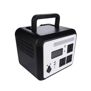
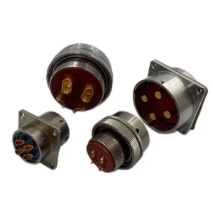
Explore our elite range of power supplies, industrial high-speed connectors, and hybrid energy storage devices engineered for modern high-performance architectures.
Deep-dive research on why this specific component acts as the fundamental building block of decoupling, noise filtering, and energy management circuits globally.
In electronic hardware engineering, the 104m capacitor stands out as one of the most ubiquitous components, yet it demands strict design precision. The "104" designation refers to the capacitance value: 10 followed by four zeros in picofarads (pF), which equals 100,000 pF, 100 nF, or 0.1 µF. The letter "M" indicates a standardized industrial tolerance parameter of ±20%. This configuration is widely deployed across a range of applications, from basic bypass functions to complex high-speed impedance matching networks.
Operating as an ODM exporter, Dynalink Electronic Technology Co., Ltd. addresses the market requirement for high-reliability 104m capacitors, including multilayer ceramic capacitors (MLCCs) and current impulse capacitors (such as the MKMJ series). These components are designed to manage modern high-frequency electronic environments. Our manufacturing facilities adjust parameters like equivalent series resistance (ESR) and equivalent series inductance (ESL) to optimize performance, preventing voltage spikes and EMI/RFI interference in sensitive integrated circuit (IC) setups.
When utilizing 104m capacitors for decoupling, they act as localized energy reservoirs. They supply rapid, transient current demands to digital logic ICs, preventing voltage sags on the power distribution network (PDN). Our design iterations focus on maximizing self-resonant frequencies (SRF), ensuring that the capacitor behaves as a capacitive element rather than an inductive bottleneck in gigahertz-range microcontrollers and processors.
| Characteristic / Parameter | Value / Industrial Standard Range | Dynalink Premium Performance Spec |
|---|---|---|
| Capacitance Value (104) | 100,000 pF (0.1 µF / 100 nF) | Guaranteed 0.1 µF at 1 kHz, 1.0 Vrms |
| Tolerance Code (M) | ±20% | Available in ±10% (K) and ±20% (M) options |
| Dielectric Code Options | X7R, X5R, Y5V, NPO / COG | High-performance X7R (Class II, Temp-stable) |
| Voltage Range (VDC) | 6.3V - 100V (Standard), 250V - 2kV+ (High Voltage) | Customized up to 3 kV for automotive and power grid installations |
| Equivalent Series Resistance (ESR) | < 50 mΩ (Typical) | Ultra-low ESR < 15 mΩ for high-frequency bypass |
| Operating Temperature Range | -55°C to +125°C (X7R Profile) | Stable performance across -55°C to +150°C for custom aviation grades |
How the 104m capacitor meets specialized hardware standards across varied global and local industrial sectors.
In modern drone avionics, power distribution systems face constant high-frequency ripple current from brushless motor ESCs (Electronic Speed Controllers). The 104m MLCCs are crucial for local filtering on power rails, ensuring that GPS modules, flight controllers, and RF telemetry systems remain free from electromotive noise.
Next-generation computing hardware requires fast power transient responses. High-speed multi-phase VRMs (Voltage Regulator Modules) flanking server CPUs and TPUs utilize dense matrices of X7R 104m decoupling capacitors. These arrays help maintain voltage stability within millivolts of target levels, supporting high-throughput workloads.
In heavy industrial settings, PLC inputs and motor control drives are exposed to transient voltage spikes, electromagnetic interference, and thermal cycling. Our robust 104m capacitors filter out signal noise on analog interface cards and prevent logic errors under continuous operating conditions.
Staying ahead of global engineering shifts by transitioning to ultra-thin materials and high-density dielectric formulations.
To address the demands of next-generation device integration, our R&D team is working to reduce dielectric thickness to under 0.5 microns. This allows for higher capacitance values within smaller case sizes (down to 0201 and 01005 footprints) while maintaining the target dielectric strength.
Using advanced nickel and copper co-firing processes instead of precious metals helps optimize production costs. It also reduces equivalent series resistance (ESR) and improves performance under high-speed signal transitions.
Mechanical stress and thermal shock can cause micro-cracks in standard MLCCs, potentially leading to short circuits. Our flexible termination technology utilizes a conductive epoxy layer to absorb structural stress, satisfying automotive-grade board flex tests.
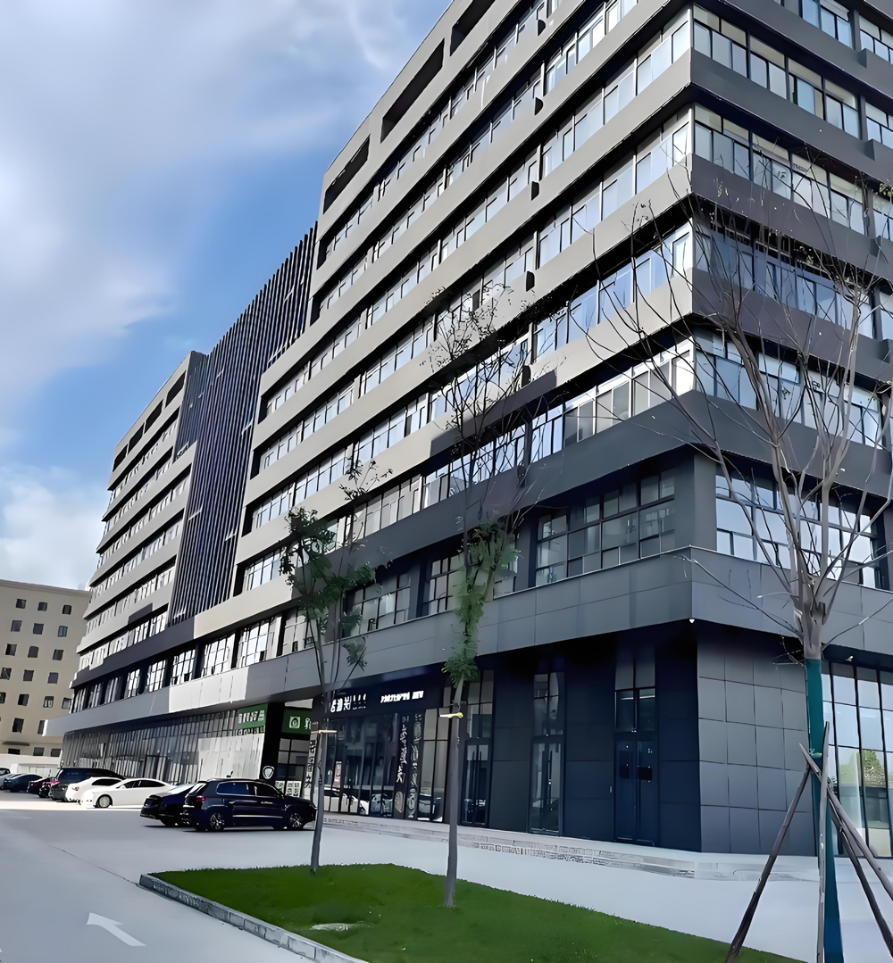
Dynalink operates as a vertically integrated manufacturer, allowing us to manage every step from powder formulation to precision high-temperature co-firing.
Our manufacturing infrastructure in China leverages established local industrial ecosystems. This integration secures access to critical raw materials—such as high-purity barium titanate and specialized electrode metals—minimizing lead times even during global supply line disruptions.
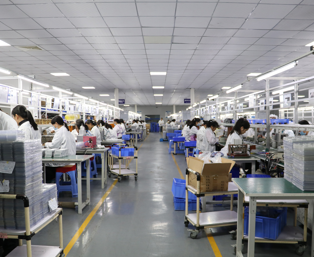
Through automated optical inspection (AOI), real-time parameter tracking, and automated sorting, we ensure that every batch of 104m capacitors exported meets international standards. Our logistics partners facilitate customs clearance and transport to North American, European, and Asian shipping ports, offering streamlined shipping options for high-volume ODM contracts.
Dynalink adheres strictly to international environmental, safety, and reliability systems to ensure global product compatibility.
Operating in industries like aviation, medical equipment, rail systems, and new energy vehicles requires strict adherence to quality standards. We perform rigorous environmental stress screening (ESS), including temperature cycling, damp heat testing, and high-temperature load life testing. This ensures our components operate reliably under harsh field conditions.
Our manufacturing plants run in accordance with three recognized ISO frameworks, ensuring process traceability, worker safety, and minimal environmental footprint:
Environmental Management System
Quality Management System
Occupational Health & Safety
Direct technical answers addressing the most common queries from design engineers and procurement departments globally.
It indicates a capacitance value of 0.1 microfarads (µF), or 100 nanofarads (nF), with a tolerance level of ±20%. The "10" represent the base digits, "4" indicates the multiplier (10,000), and the "m" signifies the standard tolerance class code.
We typically manufacture these capacitors using Class II X7R dielectrics, which offer stable performance from -55°C to +125°C. For less demanding consumer electronics, we also offer X5R or Y5V configurations depending on customer cost targets.
Yes. Every batch of 104m capacitors exported by Dynalink is fully compliant with lead-free standards, RoHS, and REACH protocols, making them suitable for import into the European Union and North America.
It provides a low-impedance path to ground for high-frequency noise currents. Positioned close to the power pins of an IC, it bypasses transient noise, maintaining clean signal lines and voltage stability.
We supply a variety of sizes, from surface mount device (SMD) footprints like 0201, 0402, 0603, 0805, to 1206, as well as radial leaded formats for legacy applications and power electronic modules.
Typical lead times for standard parameters range from 2 to 4 weeks. Custom electrical specifications or specialized testing procedures may require 6 to 8 weeks depending on the order size.
Yes. Dynalink offers automotive-grade MLCCs that comply with AEC-Q200 testing requirements, making them suitable for body control electronics and EV charging systems.
Yes, we design and manufacture capacitors across a range of working voltages, from low-voltage digital circuits (6.3V, 10V, 16V, 25V, 50V) up to kilovolts for power electronic systems.
Complete your supply procurement with our collection of industrial power solutions and precision connector interfaces.