Explore our premium grade pin header series and high-reliability connectors engineered to meet rigorous electrical standards.
A comprehensive analysis of KiCad design integration, electrical optimization, and precision board-to-board layout implementation.
In modern electronic systems design, the gap between virtual schematic capture and physical manufacturing remains a key challenge for hardware engineers. Using open-source Electronic Design Automation (EDA) suites like KiCad has gained massive traction across automotive, medical, industrial, and aerospace fields. However, the performance of high-density circuits depends directly on the reliability of the physical connectors—specifically pin headers and sockets.
Our specialized KiCad Pin Header series addresses this issue. By aligning physical connector tolerances with standard KiCad schematic libraries and exact 3D STEP models, we ensure that the transition from design to PCB layout, and finally to high-volume assembly lines, is seamless. When routing 1.27mm, 2.0mm, or 2.54mm pitch connectors, mechanical fit and electrical signal integrity must be guaranteed.
With high-speed differential signal pathways, power routing constraints, and mechanical shock absorption in mind, our manufacturing process maintains tight quality tolerances. As a leading manufacturer and global exporter, Dynalink Electronic Technology Co., Ltd bridges the gap between EDA models and robust hardware implementation.

Dynalink Electronic Technology Co., Ltd (DL), established in 2007, currently has a workforce of over 800 employees, among which more than 200 are technical staff. We are a technology-driven design and manufacturing enterprise specializing in power supplies, energy storage capacitors, and connectors.
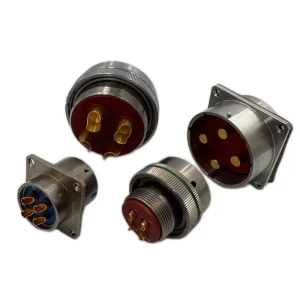
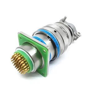
With continuous investment in research and development and strong innovation capabilities, the company has built a complete industrial chain encompassing material research and development, product design, and precision manufacturing. Thanks to the advantages of high reliability and excellent performance, its products are widely used in key fields such as aviation, aerospace, shipping, railways, new energy vehicles, the medical industry, drones, and robots, providing customized solutions for customers.
Providing custom development systems and high-reliability interconnect solutions across key industrial verticals.
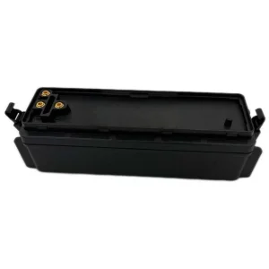
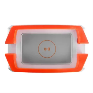
In the field of drones, our high-density connectors ensure efficient battery charging/discharging and stable operation of power systems under extreme mechanical vibration.
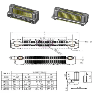
For data centers, high-speed, micro-pitch pin headers and connectors guarantee low-loss transmission of massive data and continuous, reliable operation of server units.
In industrial automation scenarios, connectors with robust chemical and temperature protection shield equipment from degradation in harsh, high-temperature environments.
Relying on our self-developed intelligent design platform, we quickly process custom length, plating, and shroud requirements, providing rapid 3D CAD/STEP generation.
We actively invest in next-generation solid-state battery terminals, ultra-high-density capacitors, and low-loss contacts to prepare for future aerospace and automotive platforms.

Taking quality as our shield, we continuously optimize manufacturing processes, electrical tolerances, and testing protocols to forge industry benchmark products.
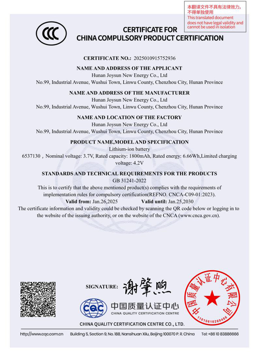
We operate under strict global management framework compliance to guarantee uniform component reliability.

Environmental Management System Certificate

Quality Management System Certificate

Occupational Health & Safety Management System


Critical board-level factors for matching layout designs to manufacturing standards.
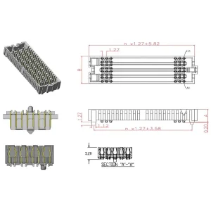
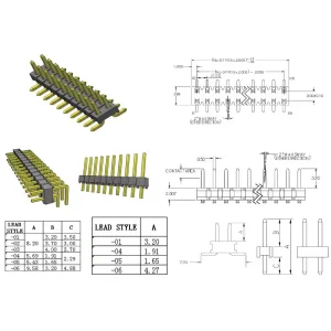
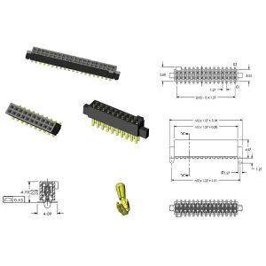
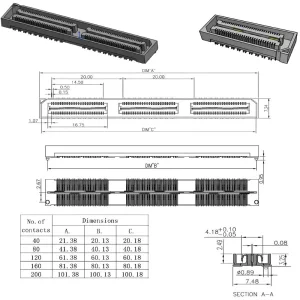
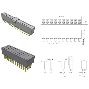
When designing circuit boards with KiCad EDA, choosing the right header layout is crucial for manufacturing efficiency and signal performance. Standard spacing options like 1.27mm, 2.0mm, and 2.54mm dictate the clearance limits and trace routing options. Below are the key design rules and mechanical details for board layout integration:
For compact embedded hardware, IoT devices, and modular sensors, the 1.27mm pitch series reduces the board footprint by 50% compared to standard 2.54mm options. However, trace clearances in KiCad must be carefully calculated to prevent electrical shorts, particularly when routing power lines next to signals.
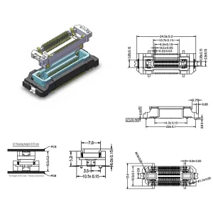
Our pin headers use high-grade polymer carriers (LCP - Liquid Crystal Polymer or Nylon-9T) capable of withstanding peak reflow temperatures of up to 260°C. This makes them ideal for modern Surface Mount Technology (SMT) assembly lines. In contrast, low-cost alternatives often deform during high-temperature reflow, causing contact misalignment.
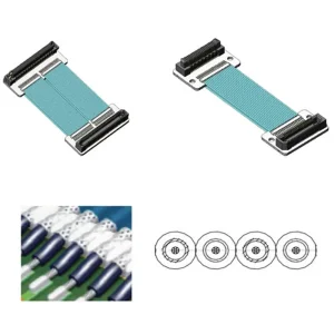
Depending on the operating conditions, we offer variable plating options. High-reliability aerospace and medical devices require thick gold plating (up to 30u") over a nickel barrier to prevent oxidation and ensure reliable contact over hundreds of mating cycles. For consumer electronics, gold-flash or selective tin-plating option provides a cost-effective, high-performance solution.
Answers to technical questions about selecting, routing, and installing pin headers.
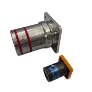
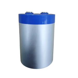
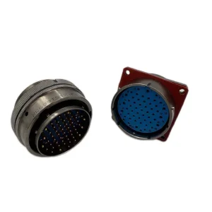
Complete your hardware design with our high-capacity energy storage, circular connections, and industrial accessories.